TEN350The waveform that hijacked the IEC lightning standards
What is a "spark gap" surge protective device?
A spark gap is a device which is capable of passing the IEC Class I test consisting of a 10/350 waveform impulse of unrealistically high peak current, charge, and specific energy.
That is the most charitable thing you can say about it. Its slow response time, high let-through current, and explosive emissions make it a poor choice for protecting sensitive electronic equipment.
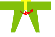
Mechanically, a spark gap consists of two pieces of metal (electrodes) insulated by a gap filled with gas or air. A transient of sufficient magnitude to break down that insulation causes a spark to jump between the electrodes. The resulting electric arc is quite conductive and hopefully shunts the surge energies to ground.
Unfortunately, the same conductive arc also passes excessively high levels of current through to the downstream electronic equipment. It also stresses the AC power system by short-circuiting it.
The spark gap concept is not new. Spark gaps were used successfully to protect different kinds of structures before the advent of integrated circuits and sensitive electronics. But times change and modern electronics are too sensitive to be protected by spark gaps.
Crowbars
IEC 62305, somewhat indelicately but accurately, classifies the spark gap arrestor as a crowbar device.
The standard writers may have really put their collective finger on something there. A crowbar is an iron or steel bar resembling a crow (the bird on the right) that uses brute force to pry boards apart and generally break things. A crowbar circuit is a type of electrical circuit used to prevent an overvoltage condition on a power supply from damaging the connected circuits. The term is descriptive --it derives from the rather explosive short-circuiting effect caused by dropping a crowbar across the output terminals of a power supply. Just as a crowbar is not a very useful tool for repairing broken televisions or cell phones, so is its "brute force" character not very effective at protecting electronic equipment from lightning.
Spark Gap Dangers and Drawbacks
They are slow to conduct because they require high initiating voltage to form the arc, typically as high as 3,000 to 4,000 volts. (Even the so-called triggered spark gaps, under actual field conditions, will not fire before 2500 to 3000 volts.)
Voltage surges below 2500 volts may damage the downstream electronics while the spark gap sits there without responding.
In some situations they are difficult to turn off after the transient has ended.
Shorts out the AC power system when spark gap operates. The short circuit condition continues until the 50/60 herz AC line current goes through the next zero crossing. This may be as long as 16 milliseconds. During this time, large amounts of current flow through the downstream electronic equipment.
Its resulting short-circuit faults cause mechanical shocks to high current power systems.
When the spark gap operates, the high di/dt of the resulting AC follow-through current can cause problems.
When transient overvoltages with relatively small magnitudes of dV/dt appear across the spark gap, the gap conducts several microseconds or more after the overvoltage has exceeded the nominal firing voltage of the gap. Overvoltages of larger magnitudes will cause a somewhat lesser (but equally significant) delay after the nominal firing voltage has been reached.
Some spark gaps emit flames and ionized gases during clearing of the AC fault current causing potential fire hazard. Care must be taken never to install spark gaps close to flammable or explosive materials.
Spark gaps are often unreliable, either failing to strike an arc when needed or failing to turn off afterwards, in the latter case due to material failure or contamination by dust or salt.
A single lightning flash of sufficient charge (or several smaller flashes) can degrade/erode the spark gap electrodes such as causing pitting to occur on the arrestor's electrodes. Spark gaps are also adversely affected by the shock waves of their own discharges.
Risk of premature in-line fuse rupture without any alarm indications.
Of great concern is the relatively slow response time (as long as microseconds in some cases) and high initial let-through voltage (which can be as high as 4-6kV.)
Since a spark gap is incapable itself of providing a satisfactory protection level for electronic equipment it must be used in conjunction with MOV-based SPDs. There are major problems associated with combining the two technologies. Each year or so spark gap manufacturers announce they’ve solved the coordination problems that they hadn’t admitted existed the previous year.
Spark gap arrestors have been called by many different names: expulsion arrestors, modified expulsion arrestors, air gaps, gas gaps, self-extinguishing gaps, triggered spark gaps, spark-gap lightning arrestor, Type 1 arrestor, Type 1+2 arrestor, encapsulated spark gaps, spark gap with quenching aid, combination arrestor, to name a few. The politically correct designation these days is "lightning arrestor." The surge suppression process is the same in all types. And all types produce follow-through currents.
Spark gaps respond much more slowly than MOV protectors. MOV surge reaction time is three orders of magnitude faster than that of a spark gap arrestor. MOVs react in nanoseconds, indicated as 10 to the minus 9th (1E-9) seconds. Spark gap arrestors react in microseconds, indicated as 10 to the minus 6th (1E-6) seconds. When the two are installed together, great efforts are made to get the Class 1 spark gap protector to fire before the Class 2 MOV protector responds. The largest MOV based protectors used in conjunction with spark gaps are typically rated at only 40kA. These so-called "Class II MOV protectors" are too small and inefficient to conduct the full lightning current. The major spark gap players each have their own-patented “solutions” to this "coordination" problem and the IEC 62305-4 standard devotes 1/3 of its pages trying to “standardize” this coordination. But all in vain. The stock solution is to rely on series inductances that will hopefully get the spark gap to fire quicker. The inductance sometimes relies on the building's wiring and other times is directly added by auxiliary components sold by the spark gap manufacturers. Results will always be inconsistent because they are dependent on peak currents and rise times. The CIGRE 2013 Technical Brochure points out that peak currents vary between 2kA and 300kA while rise times fluctuate between 10 and 400 kA/μs.
Studies show that the explosive operation of spark gap SPDs can produce damaging effects on the inverters and charge regulators of PV systems. Hence spark gaps are no longer recommended for protecting PV systems. (Even the spark gap manufacturers rarely dare to recommend their spark gaps for use in PV applications.)
You sometimes hear the claim that spark gaps will react in less than 50 nanoseconds. If that were true it would still be 1,000% slower than an MOV. But "reacting" is one thing. "Firing" is another. For a spark gap to fire within 50 nanoseconds is conceivable only under certain very fortuitous conditions--such as when all the planets go into perfect alignment.
The spark gap's worst drawback we have saved to last. CIGRE 2013 Technical Brochure informs us that over 80% of lightning consists of 3-5 closely spaced impulses. Following a high current sparking, the gap between the electrodes stays "hot" for some time. During this "recovery" period the spark gap is out of spec and cannot respond effectively to the subsequent strokes in the lightning flash.
Comparison with MOVs
All the above problems are avoided by MOV-based SPDs
The only "advantage" a spark gap SPD has over an MOV-based SPD is its ability to pass a singe-impulse 10/350 waveform test. And as is shown throughout this website, this is a spurious advantage because the 10/350 waveform is an "irrelevant" impulse.
CIGRE's 2013 Technical Brochure 549 has corrected the misconception that the 10/350 waveform is the waveform of a lightning first stroke--because it isn't. That is why it's accurate to call the 10/350 waveform irrelevant.
A spark gap protector (because it responds slowly and is a crowbar device) can endure a high amplitude 10/350 waveform better than an MOV-based SPD. But spark gaps don't do very well protecting electronic equipment from actual lightning. An MOV protector responds 1000 times faster and actually absorbs part of the energy in the process of clamping the lightning transient voltage down to safe levels. MOVs don't do so well with a 10/350 waveform because they absorb part of the energy, but they are far more effective than spark gaps at protecting electronic equipment from actual lightning.
Because everyone wants stronger, more effective, SPDs protecting their equipment, we consider it disingenuous for standards to treat MOV-based SPDs as second class citizens when in fact they are superior at handling direct lightning and don't require all the complex coordination machinations of the spark gaps.
Forward-looking spark gap manufacturers should be viewing CIGRE's 2013 report as an opportunity. But to take advantage of it, they'd have to step up and take the Spark Gap Challenge. You can read all about it here (including its fascinating history.)
 That is the most charitable thing you can say about it. Its slow response time, high let-through current, and explosive emissions make it a poor choice for protecting sensitive electronic equipment.
Mechanically, a spark gap consists of two pieces of metal (electrodes) insulated by a gap filled with gas or air. A transient of sufficient magnitude to break down that insulation causes a spark to jump between the electrodes. The resulting electric arc is quite conductive and hopefully shunts the surge energies to ground.
Unfortunately, the same conductive arc also passes excessively high levels of current through to the downstream electronic equipment. It also stresses the AC power system by short-circuiting it.
The spark gap concept is not new. Spark gaps were used successfully to protect different kinds of structures before the advent of integrated circuits and sensitive electronics. But times change and modern electronics are too sensitive to be protected by spark gaps.
That is the most charitable thing you can say about it. Its slow response time, high let-through current, and explosive emissions make it a poor choice for protecting sensitive electronic equipment.
Mechanically, a spark gap consists of two pieces of metal (electrodes) insulated by a gap filled with gas or air. A transient of sufficient magnitude to break down that insulation causes a spark to jump between the electrodes. The resulting electric arc is quite conductive and hopefully shunts the surge energies to ground.
Unfortunately, the same conductive arc also passes excessively high levels of current through to the downstream electronic equipment. It also stresses the AC power system by short-circuiting it.
The spark gap concept is not new. Spark gaps were used successfully to protect different kinds of structures before the advent of integrated circuits and sensitive electronics. But times change and modern electronics are too sensitive to be protected by spark gaps.  IEC 62305, somewhat indelicately but accurately, classifies the spark gap arrestor as a crowbar device.