TEN350 The waveform that hijacked the IEC lightning standards

IEC 62305-1
NAME:
Protection against lightning - Part 1: General principles.
AUTHORS:
IEC Technical Committee TC 81 Lightning Protection.
INFO:
IEC 62305-1 shows in detail how thoroughly the spark gap & 10/350 test have insinuated themselves into every aspect of the IEC lightning protection standards.
10/350 TIMELINE:

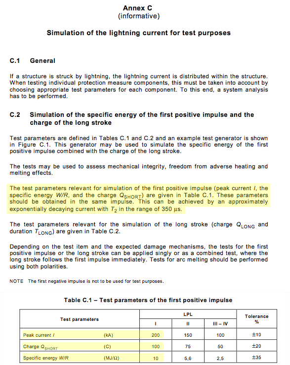
The five parameters on which the Class 1 Test is based can be traced back as follows:
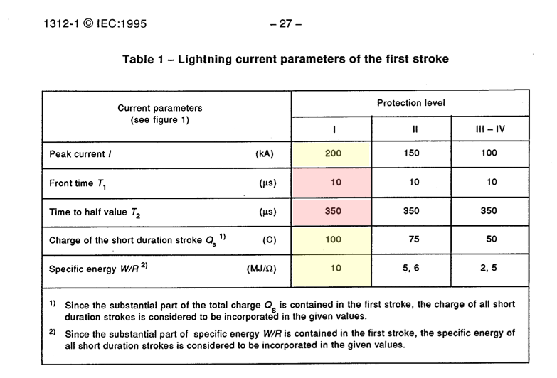
1995: IEC 61312-1 (parameters come directly off the Hasse 10/350 chart)
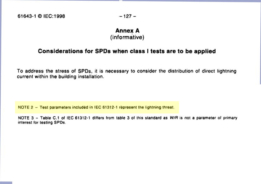
1998: IEC 61643-1 (parameters taken from IEC 61312-1)
Roll your cursor over the 62305-parameter chart to the right and you'll see exactly from where those parameters spring.
REFERENCES:
This standard cites the 2 Berger/Anderson CIGRE Electra articles in hopes they would provide some authority for the 62305-1's 10/350 waveform. As shown on the CIGRE pages of this web, the CIGRE Technical Brochure 549 invalidates any legitimacy the 10/350 waveform was ever thought to have had.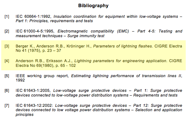
LIGHTNING PARAMETERS:
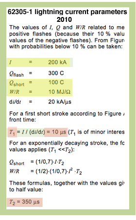
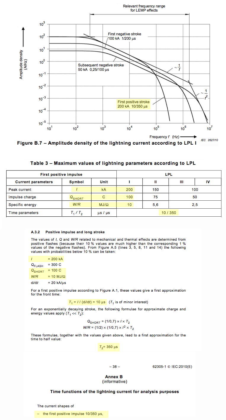
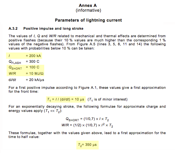
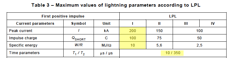
IEC 62305-1 contains five annexes. Each approaches the subject of lightning parameters in its own way. Together they seek to persuade the reader that all five of the Hasse lightning parameters must be used, and that they must all be used together. The 5 parameters can be seen highlighted in green in the 62305-1 chart to the right. Move your curser over it and you'll see the actual source of those parameters: the 1982 Hasse chart.
Annex A re-introduces the five Hasse parameters. See Section A.3.2.
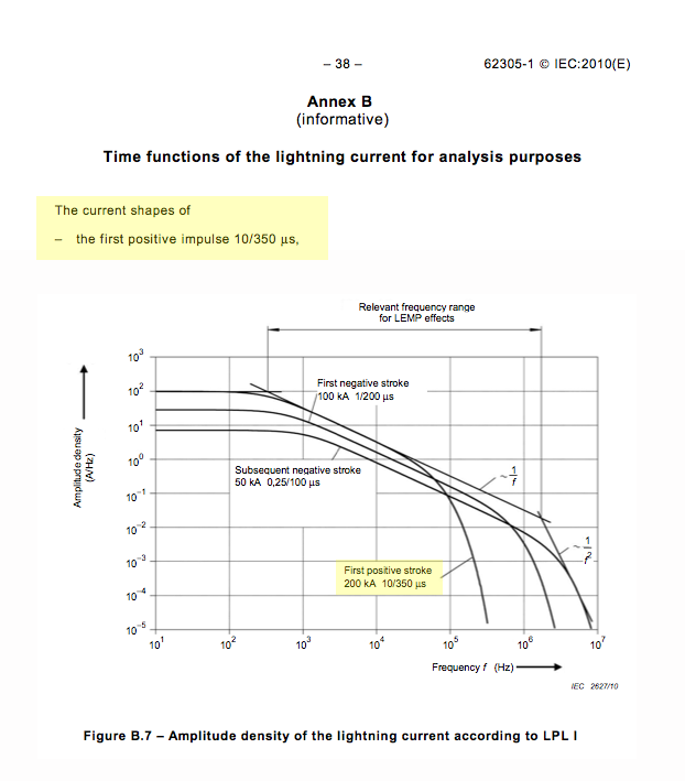
Annex B drives home the importance of the duration factor: 350 microseconds is a MUST.
LIGHTNING PROTECTION LEVELS --The big broken promise:
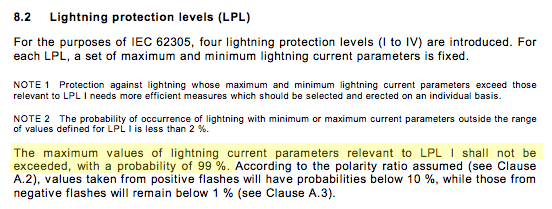
A lightning protection level according to IEC 62305-1 (3.39) is a set of lightning current parameters which is not supposed to be exceeded in naturally occurring lightning. Which lightning protection level you choose determines the design of your protection measures. Section 8 of this standard warns us that the entire 62305 series hangs or falls on its system of LPLs (lightning protection levels.)
The most rugged level (LPL 1) uses the parameters highlighted here and promises us that less than 1% of lightning will fall above those parameters. So we're being promised a 99% success rate at handling lightning if we agree to suffer through the trouble and indignity of spark gaps and Class one tests. And you know that if this promise had been kept, nobody would be complaining about this standard and this website would have never been created. Simple fact, though is that the promise is not worth the paper it's written on. (And that's not very much because the IEC no longer provides paper copies of standards.)
Let's say we agree this standard rises and falls on the validity of its LPL concept. And let's say (as shown elsewhere on this web) that lightning protection installations based on this standard can have failure rates up to 1,000% higher than we were promised. Where does that leave the standard?
More on Lightning Protection Levels here.
LIGHTNING PROTECTION ZONES:
Although rolled out in much more detail in 62305-3, the LPZ System is introduced here. See Fig. 3. The structure is the white box surrounded by green. The green area designates locations (Zone 0) where lightning can strike. The two basic premises of the LPZs are: 1)When lightning hits anywhere in the green region the current created must be characterized by a 10/350 waveform. 2) Only spark gap protectors may be installed in the green area or on the border between green and white. Of course, if the 10/350 waveform doesn't exist, and spark gaps do such a poor job at protecting electronic equipment against surges, then what can be said on behalf of the LPZ system?
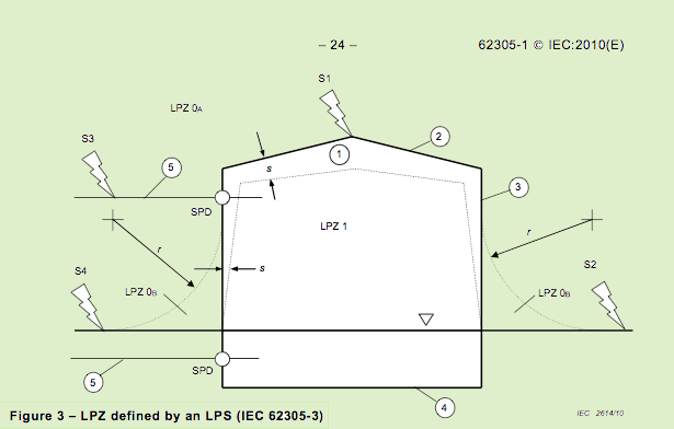
Not surprisingly, although this version of the LPZ system has been in widespread continuous use for over 20 years, there are apparently no statistical studies to prove its effectiveness.
THE ROLLING SPHERE METHOD
According to Section 8.2 it is the 10/350 parameters incorporated into the Lightning Protection Levels that are used to calculate the radius of the rolling sphere.
OTHER SPIN-OFFS FROM 10/350 WAVEFORM:
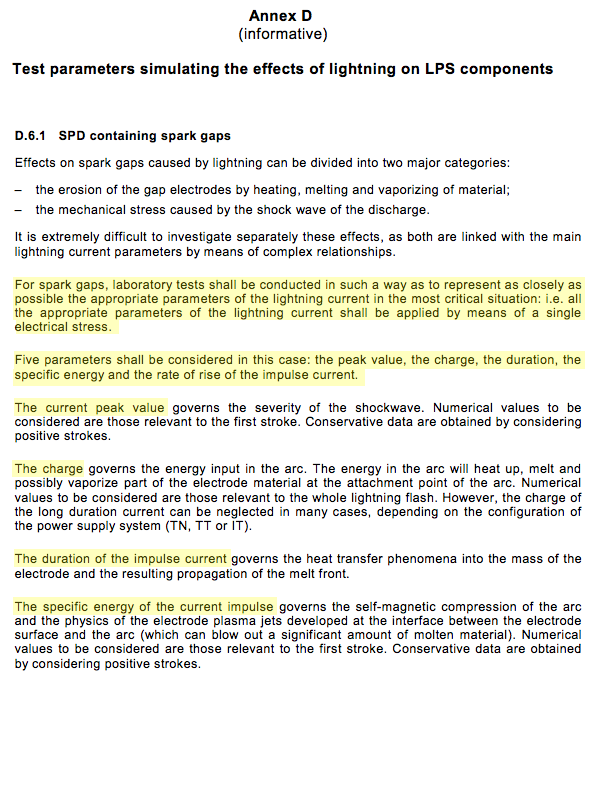
Section 8.2 tells us that the 10/350 parameters "are used to design lightning protection components (e.g. cross-section of conductors, thickness of metal sheets, current capability of SPDs, separation distance against dangerous sparking) and to define test parameters simulating the effects of lightning on such components."
SIMPLE SOLUTION
The many anomalies caused by the imposition of the arbitrary and unhelpful 10/350 waveform would vanish if mandatory use of 10/350 was simply removed from standards.
Back to IEC standards page